PiKey-10 Installation
PiKey-10 Installation Kit
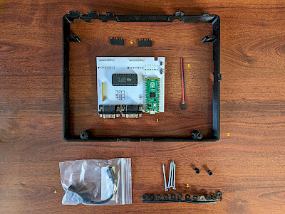
The PiKey-10 basic installation kit consists of:
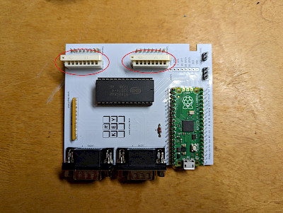
- The PiKey-10 board which plugs into the keyboard header connectors on the mainboard and provides the Atari-style joystick ports and USB keyboard jack
- A 3D-printed riser which fits between the MC-10 case halves to provide extra space inside the MC-10 for the PiKey-10 board and a location to securely mount the board
- Longer MC-10 case screws and 3D-printed spacers appropriate for proper installation of the 3D-printed riser to the PiKey-10 and for mounting between the case halves
- A USB OTG adapter to provide a USB type A socket for connecting a wired keyboard
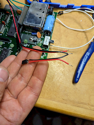
- A power cable to be soldered to appropriate taps of the 5V DC regulator inside the MC-10, necessary to provide power to the PiKey-10
- Two 8-pin female header connectors which may optionally be used to replace the existing white keyboard ribbon cable connectors. Relocation of these connectors enables the continued use of the original MC-10 keyboard.

Optional hardware which may be included with PiKey-10:
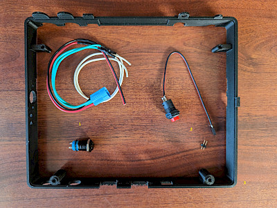
- A front-panel power switch and detachable wiring harness/pigtail
- A front-panel reset button, wiring harness/pigtail, and 2 pin header connector
- Alternate riser with openings for installation of power and reset buttons and a CoCoVGA button board

Optional hardware which is not included with PiKey-10, for the purposes of expanding internal MC-10 SRAM from 4kB to 8kB - see MC-10 Internal Memory Upgrade.
Necessary Tools
- Soldering iron/solderpen and solder
- For removing the RF shield, a soldering gun, solder sucker and wick are preferred, although the soldering iron listed above may suffice
- For optionally transplanting the keyboard header connector to enable the original MC-10 keyboard, a vacuum desoldering tool is preferred, although the soldering iron listed above with a solder sucker and wick may suffice
- 3/16" nut driver or socket and driver
- Phillips screwdriver
- Needlenose pliers or tweezers
- Dental pick or tiny flat screwdriver
- For installation of optional power/reset buttons, a dremel or drill and bits for cutting a trace
PiKey-10 Installation Procedure
NOTE: At a minimum, proper installation of PiKey-10 requires desoldering of the internal shield and soldering of two wires to the 5V regulator.
- Disconnect the MC-10 from all cables and other expansion devices
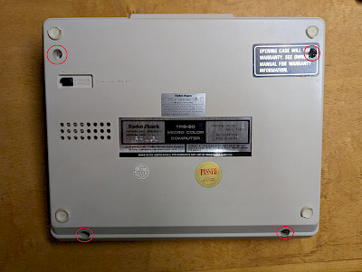
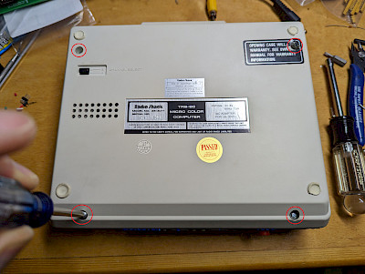
- Turn the MC-10 upside down and remove the 4 screws holding the case together
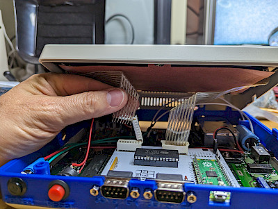
- Gently pull the case halves apart - NOTE THAT THE KEYBOARD RIBBON CABLES WILL KEEP THE CASE HALVES FROM SEPARATING FULLY
- Reach between the case halves and open the white "guillotine" connectors to which the keyboard ribbon cables are connected
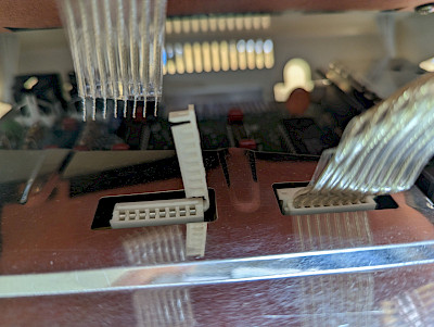
- Gently pull the keyboard ribbon cables out of the white connectors and set the top half of the case aside
- Remove the 3 screws holding the MC-10 mainboard in the bottom half of the case
- Remove the MC-10 mainboard from the bottom half of the case and set the bottom half of the case aside. Note that the channel selector switch may have a black cover over it that could fall off. It is best to remove this from the switch and set it aside for reinstallation.
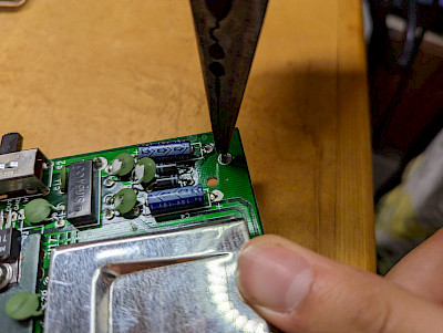
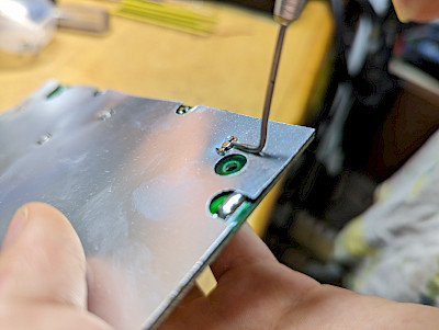
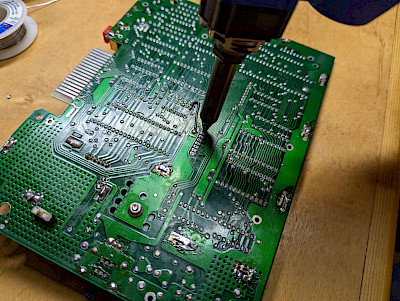
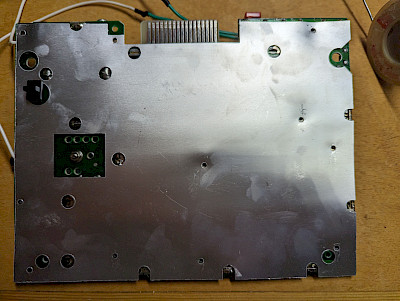
- Remove the shiny reflective shield from the underside of the MC-10 mainboard. To do this will require that the 11 clips holding it in place be removed. Some of these can be removed by pushing them out from the top of the mainboard using tweezers or needlenose pliers. Others will be hidden by the shield on the top of the mainboard. These can be removed by prying them away from the bottom of the mainboard partway using a small screwdriver or dental tool and then using tweezers or needlenose pliers to extract them the rest of the way. Set these clips and the shiny reflective shield aside.
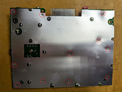
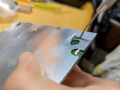
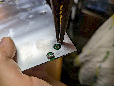
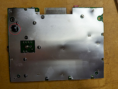
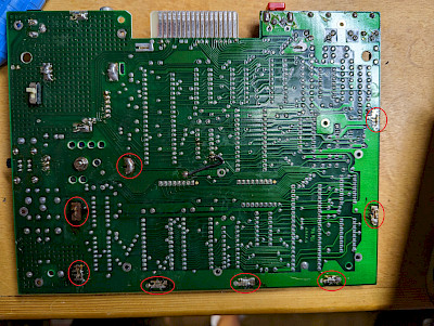
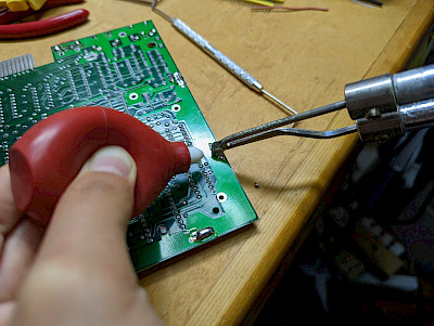
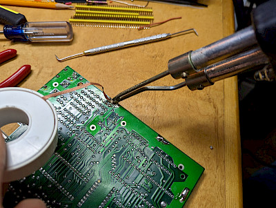
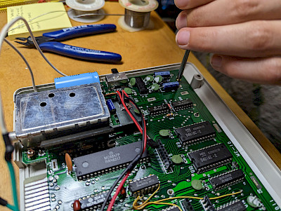
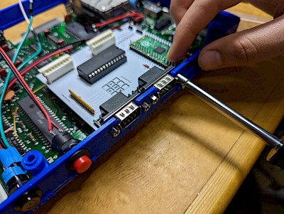
- Identify the locations of 8 solder lugs holding the large metal shield in place on the mainboard. From the bottom of the board, desolder these lugs and remove the shield. A desoldering gun or soldering gun and solder sucker or solderwick work best, but with patience, a solderpen can also do the job. Note that some lugs may be twisted and require rotation using needlenose pliers after they are desoldered in order to get them out through the slots in the circuit board. The metal shield will no longer be needed unless there is desire to reverse the installation in the future.
- Optional - retain functionality of original MC-10 chiclet keyboard
Note that this step requires non-destructive desoldering of the white "guillotine" header connectors where the keyboard ribbon cables were originally connected such that they may be moved to the PiKey-10 board. It also requires soldering of new header connectors in place of these white "guillotine" header connectors.- Carefully desolder the white "guillotine" header connectors to which the MC-10 keyboard was originally connected. These must remain intact to transplant to the PiKey-10 board.
- Optional - if installing the 8kB internal SRAM piggyback modification described on the CoCoVGA web site, consider doing that at this point.
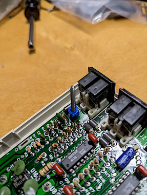
- Solder the included 8-pin female header connectors in the same position on the mainboard where the white "guillotine" header connectors were originally installed.
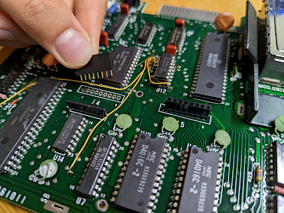
- Solder the white "guillotine" header connectors to the PiKey-10 board JYMTRX0 and JXMTRX0 pads, taking note of connector orientation. (Note that holes in the PiKey-10 boards should assist in orientation.)
- Carefully desolder the white "guillotine" header connectors to which the MC-10 keyboard was originally connected. These must remain intact to transplant to the PiKey-10 board.
- Optional - if installing an 8kB internal SRAM piggyback mod described on the CoCoVGA web site which was not done as part of optional step 10, above, consider doing that at this point.
- Optional - install front panel power switch and reset button
Note that this step requires cutting a trace on the MC-10 mainboard and soldering.- Reset:
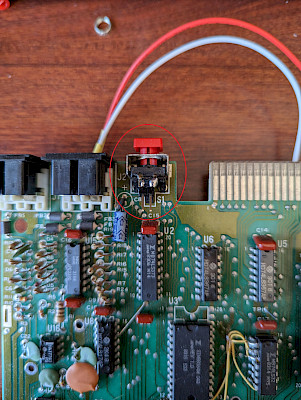
- On the top of the MC-10 mainboard, locate the red reset switch. In particular, look for the 2 metal tabs sticking towards the front of the mainboard from the top of the red reset switch.
- Solder the short side of a 2-pin header connector to these pins.
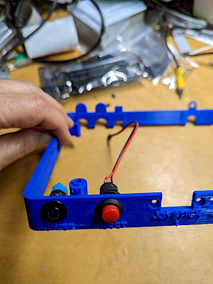
- Install the provided reset button in the front of the riser in the circular cutout marked RESET.
- When the case is assembled later, plug the reset button pigtail into this 2-pin header connector. Black/red orientation is irrelevant for this connection.
- Lighted power switch:
- Turn over the MC-10 mainboard such that the underside can be seen and identify the appropriate trace leaving the power jack. (See photo in next step.)
- Use a drill or dremel to cut this trace on the mainboard.
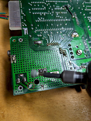
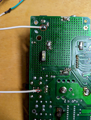
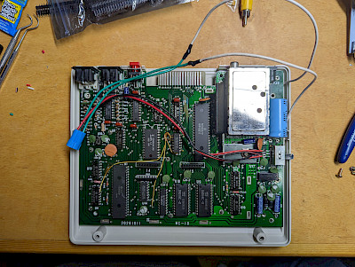
- Solder one of the white wires to the appopriate pin of the power jack. (See photo in next step.)
- Solder the other white wire to the appropriate rightmost center pin of the power switch.

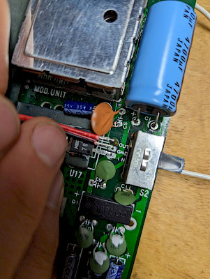
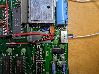
- Turn over the MC-10 mainboard such that the topside can be seen and locate the 7805 voltage regulator near the power slide switch.
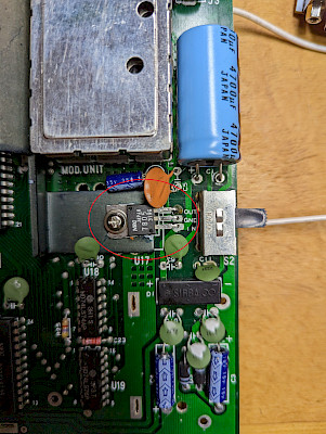
- Solder the red wire to the pin of the voltage regulator marked IN.
- Solder the black wire to the pin of the voltage regulator marked GND. This should be the center pin. (Note that this step should be combined with soldering the PiKey-10 power pigtail to GND in step 13, below.)
- Install the provided power switch in the front of the riser in the circular cutout marked POWER.
- When the case is assembled later, plug the power switch pigtail into the power switch installed in the riser.
- Reset:
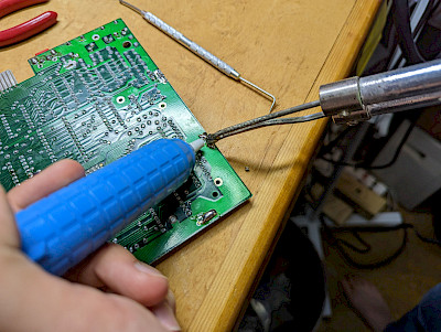
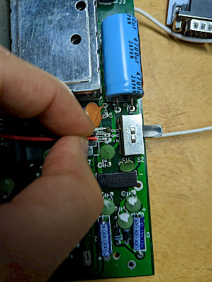
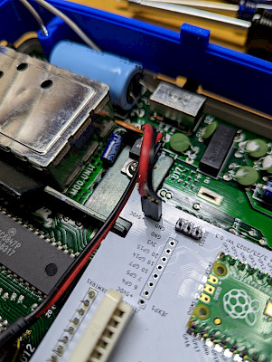
- Solder the red wire of the PiKey-10 power pigtail to the voltage regulator on the right side of the MC-10 mainboard to the leg marked OUT. Solder the black wire to the voltage regulator's center tap (marked GND). NOTE THAT IT IS CRITICAL THAT THESE TWO BARE WIRES OR THEIR SOLDER JOINTS NOT TOUCH! FAILURE TO KEEP THEM SEPARATE WILL LIKELY RESULT IN THE VOLTAGE REGULATOR SHATTERING UPON POWER-UP!
OR, with front panel power switch installation:
- Reinstall the shiny reflective shield to the underside of the MC-10 mainboard and reattach the clips that had been removed in step 8.

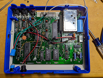
- Return the MC-10 mainboard to the bottom half of the case. Note that in the process of doing this, it is appropriate to replace the black cover over the channel selector switch if you have not already done so. If you have installed a power switch, route the wires around the edge of the mainboard but away from the case mounting tab, slide power switch, and power jack.
- Reinstall the 3 screws that hold the MC-10 mainboard in the bottom half of the case.
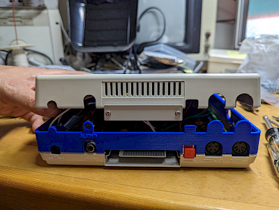
- Place the 3D-printed riser on the bottom half of the MC-10 case and place the two longer 3D-printed spacers between the rear screw holes and the riser. It may be appropriate to insert the longer screws up through the bottom of the case to keep these two spacers in place.
- Unscrew the 4 hex lugs from either side of the joystick ports of the PiKey-10 and set them aside for attachment to the 3D-printed riser.
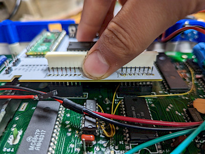
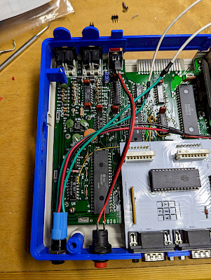
- Plug the PiKey-10 into the MC-10 mainboard either at the original white "guillotine" connectors (if still installed) or the new black 8-pin header connectors. Drop the joystick ports with their trapezoidal metal shields in place into the openings on the 3D-printed riser.
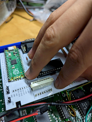
- Install the 4 hex lugs that were removed from either side of the joystick ports, attaching the PiKey-10 board to the 3D-printed riser. Take note of space between the joystick port's metal shield and the 3D-printed riser. If any gap is noticed, use the appropriate thickness(es) of the included 3D-printed washer-type spacers between the joystick port and the 3D-printed riser.
- Connect the PiKey-10 power pigtail to the JPWR1 connector on the PiKey-10. Make sure the +5VDC connects to the red wire side of the pigtail's header and the GND connects to the black wire side of the pigtail's header.
- If you have installed a power switch and/or reset button, plug these pigtails into their associated connectors.
- If your MC-10 has never been connected to memory expansions, its rear cover plate may still be installed. Remove it by unscrewing the two phillips screws that hold it in place before continuing.
- If the white "guillotine" connectors have been relocated to the PiKey-10 board, place the top half of the MC-10 case over the bottom half, open the guillotine connectors, reinsert the ribbon cable into them, and close the connectors.
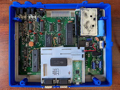
- Place the top half of the case on top of the 3D-printed riser.
- Holding the MC-10 together as well as the longer screws in the bottom rear holes, turn it over and install the longer screws in all 4 holes.
- Reconnect the MC-10 to the power supply, peripherals, the USB OTG cable, and your wired USB keyboard and 9-pin joysticks/joypads, as appropriate.


